introduce
The Internet of Things communication protocol, based on the netty framework, supports COM (serial port) and TCP protocols, supports two modes of server and client, realizes Java control of smart devices, and supports high-concurrency communication of multiple devices in a device group. Using the factory design mode, the code is highly encapsulated by inheriting and rewriting, and can be used as an SDK to provide an encapsulated interface, so that specific business developers can use the interface directly without caring about the underlying implementation of the communication protocol. Command control such as heartbeat, backlight, code scanning, card swiping, finger vein, temperature and humidity, and door lock (support multi-lock) are realized. The code is rich in comments, including examples of uploading and issuing commands, which is very easy to get started.
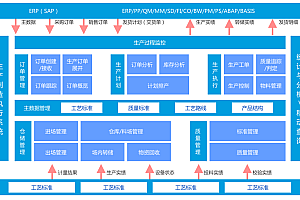
Software architecture
Software Architecture The infrastructure uses Spring Boot2.x + Netty4.X + Maven3.6.x, and logbacks are used for logs.
Installation tutorial
System: Windows 7 or above;
Install Jdk1.8 or later;
Install Maven 3.6 or later;
Import the code into Eclipse or Idea as a Maven project.
Directions for use
Description of the engineering structure:
iot-modbus //IoT communication parent project
├── doc // Document management
├── iot-modbus-client //netty communication client
├── iot-modbus-netty //netty communication sub-project
├── iot-modbus-serialport // serial communication sub-project
├── iot-modbus-server //netty communication server
├── iot-modbus-test // Use sample project
└── tools //Communication command debugging tool
For configuration files, see the application.yml files in the resources directory of the iot-modbus-test subproject
Start the file, see the App.java file of the iot-modbus-test subproject
After the service is started, the default server port is 8080, and the netty communication port is 4000
For the communication command debugging tool, see the NetAssist.exe in the tools directory
Communication instructions are Hex encoded (hexadecimal)
Instruction format
The heartbeat command (7E 04 00 BE 01 00 00 74 77 7F) is used as an example to illustrate the subscript, which starts at 0
The 0th bit is the starting character, the length is fixed to occupy 1 byte, and the fixed format is 7E
The first and second bits are the data length, which is calculated from the command letter to the data bit (i.e., from 3 bits to the instruction length – 3 bits), and the length is fixed at 2 bytes, for example: 04 00, which means that the length is 4
The third bit is a commandor, and the length is fixed at one byte, for example, BE, which indicates a heartbeat instruction
The fourth digit is the device number, which is fixed in length and occupies one byte, for example, 01, indicating that the device number is 1
The fifth bit is the layer address, and the length is fixed at 1 byte, for example, 00, which indicates that all layers of the device are not executed
The sixth bit is the slot address, and the length is fixed at one byte, for example, 00, which indicates that all slots of the device are not executed
The instruction length -3 to -2 bits is the check digit, and the CRC16_MODBUS (length, command, address, data) is used, for example: 74 77, see the :ModbusCrc16Utils.java tool class for details
The last bit is the ending character, the length is fixed to occupy 1 byte, and the fixed format: 7F
Debugging instructions
1. Find the iot-modbus-test subproject App.java file to start the server, as shown in the following figure:

Note: After the project is successfully started, the port of the server for the output of console logs is 8080. The project service name is: iot-modbus-test; The socket communication port on the server is 4000.
2. Copy NetAssist, the communication command debugging tool in the project tools directory, to the Windows desktop, double-click to open it, and configure the parameters, as shown in the following figure:

Note: Select TCP Client as the protocol type (the debugging tool is used as the client terminal for simulated hardware communication). Remote host address: Enter the IP address of the local computer; Enter the remote host port into the server port 4000; Receive and transmit encoding selection HEX; Finally, click the Connect button to connect, and the server console log output is shown in the following figure after the connection is successful:

3. The client uploads the heartbeat command to the server, as shown in the following figure:

Note: Copy the heartbeat command to the data sending window of NetAssist, and then click the send button. At this time, the server will receive the heartbeat command, as shown in the following figure:

Note: The communication connection between the client and the server needs to be maintained by the client sending heartbeat instructions to the server at regular intervals, and the sending frequency can generally be set to once every 5 seconds in the production environment. Note: During debugging, if the communication connection between NetAssist and the server is disconnected, you need to manually click the connection button of NetAssist to send a heartbeat command to the server again.
4. Use Postman to request the server to send a control single lock command to the client, as shown in the following figure:

- Note: Enter the Postman server to send a control single-lock command interface, fill in the request address and parameters: http://127.0.0.1:8080/iot-modbus-test/test/openlock/1/1, and the server console logs are output as shown in the following figure: